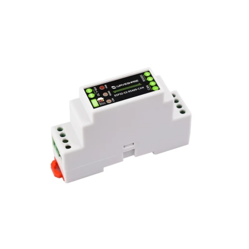



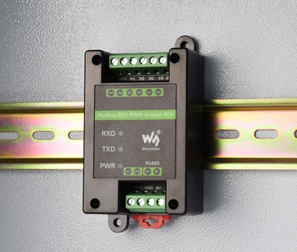
Industrial PWM output module 4-CH RS485 Modbus RTU Waveshare
Regular price:
 ・Kup teraz i zapłać za 30 dni

product unavailable

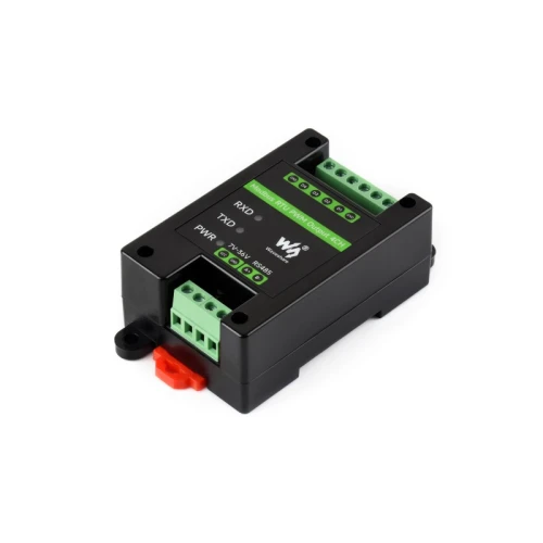
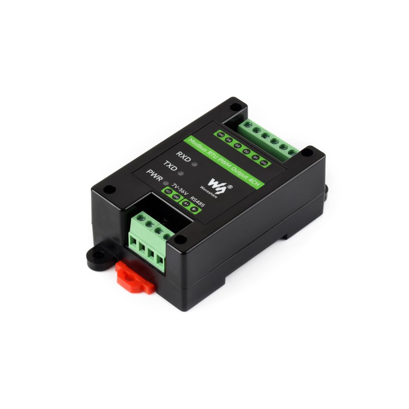
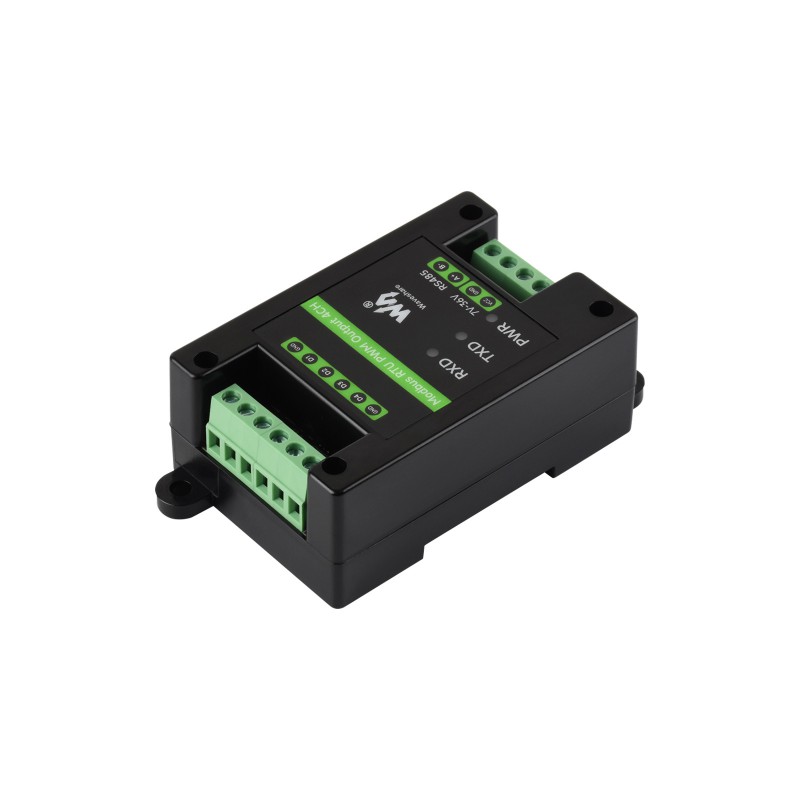
Industrial 4-CH PWM output module RS485 Modbus RTU
Industrial output module offering 4 independent PWM channels with adjustable frequency and duty cycle, controlled via RS485 interface using the Modbus RTU protocol. The device is designed for demanding industrial environments, features dual isolation (power and signal) and built-in protection, and is enclosed in a housing suitable for DIN rail mounting.
Key features:
- 4 PWM output channels with independent frequency and duty cycle adjustment.
- Communication via isolated RS485 interface using the standard Modbus RTU protocol.
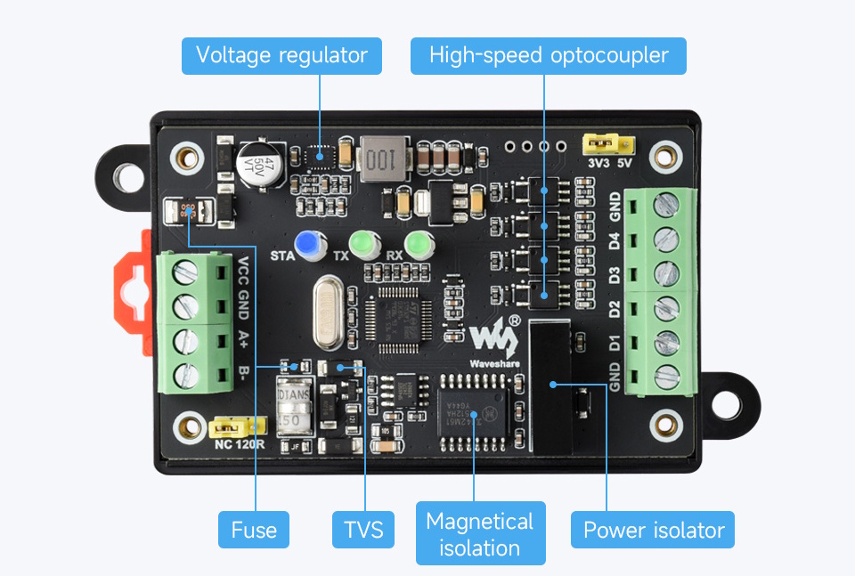
- Outputs isolated using high-speed optocouplers, with the option to change the output voltage (3.3V or 5V) using an internal jumper.
- Configurable device address (1~255) allowing for cascading multiple modules on the RS485 bus.
- Wide power supply voltage range (7~36V DC) thanks to a built-in stabilizer.
- Dual isolation: unibody for power and magnetic for signal, ensuring high resistance to interference.
- Built-in protection: polymer fuse (resettable), TVS diodes, protection against overvoltage, electrostatic discharge, and overcurrent.
- Hardware watchdog ensuring stable operation without freezing.
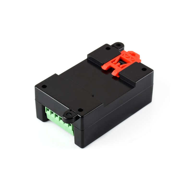
- Compact housing suitable for mounting on a standard DIN rail.
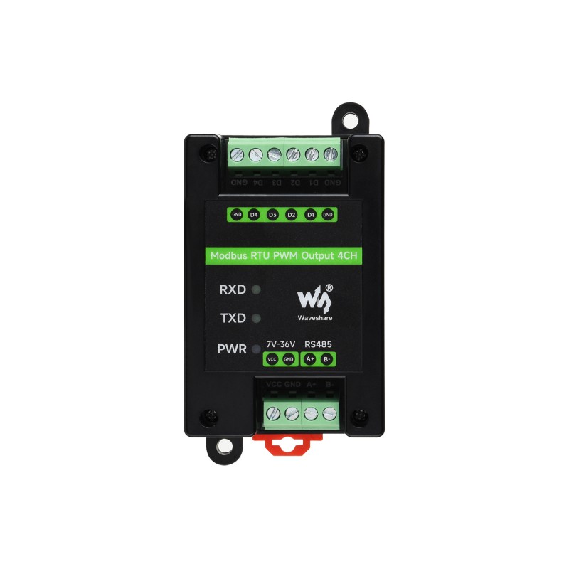
- Three LED indicators for power status and signal transmission/reception.
Basic functionality
The device allows sending commands in the Modbus RTU protocol via the RS485 bus, which enables precise generation and control of PWM output signals.

Industrial isolation and protection
The module features integrated dual power and signal isolation for RS485 communication, ensuring stable isolation voltage and strong protection against interference. Built-in TVS diodes effectively suppress overvoltage and transient voltage spikes. The device is protected against ESD. The use of a polymer fuse and protective diodes guarantees stable current parameters, making the module an ideal choice for rigorous industrial applications.
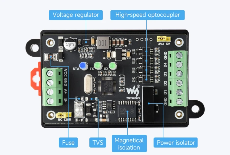
Connection diagram
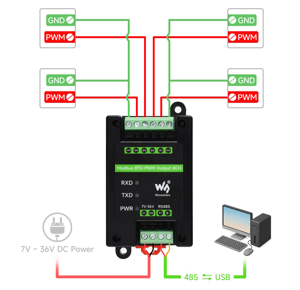
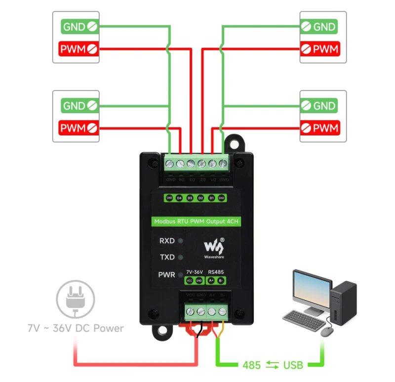
Terminals D1 to D4 are PWM signal output connectors, while GND is the power ground. The PWM output frequency range is from 1 Hz to 200 kHz. To connect the device to a computer or master controller, use an RS485 converter, connecting the signals with wires: A to A and B to B.
Address configuration
The module does not have hardware DIP switches for configuration. The device address (slave address) is assigned exclusively via software, using appropriate configuration commands sent over the bus.
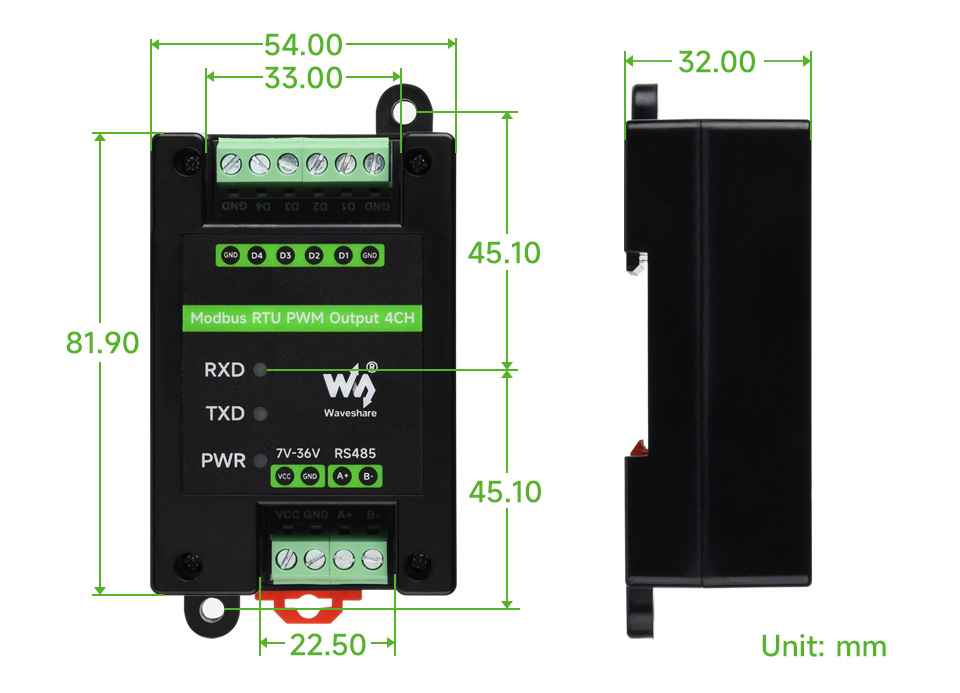
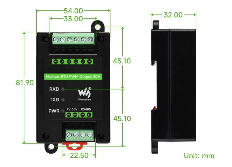
Dimensions
Technical specification
- Communication interface: RS485
- Baud rate: 4800, 9600, 19200, 38400, 57600, 115200, 128000, 256000 bps
- Default communication format: 9600, N, 8, 1
- Protocol: Standard Modbus RTU
- Power supply voltage: DC 7~36V
- Output voltage: Default 3.3V (can be changed to 5V via jumper)
- Output current: Signal level, < 30mA
- Pulse frequency: 1Hz ~ 200KHz
- Frequency resolution: 0.01Hz
- Frequency accuracy: 5‰
- Duty Cycle: 0 ~ 100%
- Duty cycle resolution: 0.01%
- Duty cycle accuracy: 5‰ (1Hz ~ 50kHz), 1% (50kHz ~ 200kHz)
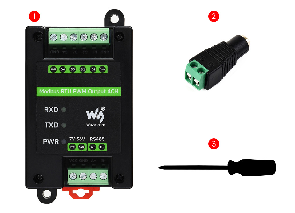
Package contents
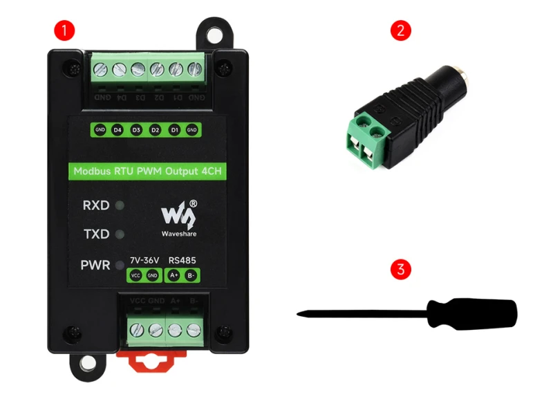
- Modbus RTU PWM Output 4CH module x1
- Power terminal adapter x1
- Screwdriver x1
 Shipping costs
The price does not include any possible payment costs
Shipping costs
The price does not include any possible payment costs
Popular products