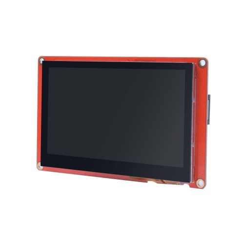
Nextion Enhanced NX3224K028 - Generic 2.8'' HMI Touch Display
Regular price:
 ・Kup teraz i zapłać za 30 dni
product unavailable
The Nextion Enhanced NX3224K028 is the perfect display for quick HMI projects using readily available tools.
The display is controlled via the UART serial bus. The display is recommended for Arduino, Raspberry PI and systems with ESP8266 microcontrollers.
If you need to quickly design an interface with buttons, charts, various controls and allowing easy operator input then you will find the answer in the Nextion series products.
Specifications of the Nextion Enhanced NX3224K028 display shown:
- Size: 2.8″
- Resolution: 320*240
- Touch panel: resistive
- Number of colours: 65536
- Flash memory: 16 MB
- RAM: 3584 Byte
- MCU clock: 48 MHz
- EEPROM memory: 1024 Byte
- Number of GPIOs: 8
- Real-time clock: YES
- Enclosure: NO
Nextion Editor
The graphic layout of the screen and the functional elements can be designed very easily and quickly with a free program on your computer.
Each screen can contain a number of functional elements, known as widgets, which include:
- Text: a text field which can be modified while the display is running.
- Number: a numerical field which can be modified both via the microcontroller and the interactive keyboard on the display.
- Button: a button. Both pressing and releasing a button is easy to register via the microcontroller.
- Progressbar: a progress bar. The value of this bar can be easily set with the appropriate command.
- Picture: allows the creation of a screen background or the insertion of parts of an image anywhere on the screen.
- Gauge: is an analogue pointer with a single pointer.
- Waveform: used to draw up to four graphs.
- Slider: a slider with which you can set various parameters, variables in the programme.
- Checkbox : A checkbox. Each touch changes it to the opposite state.
Using the mouse, insert the functional elements that you will need on the screen and determine their size on the screen and position.
The finished project prepared in the Nextion Editor software can be transferred to the display in two ways:
- Uploading the appropriate project file to an SD card and inserting it into the display. When power is applied, the display will automatically load the design into its Flash memory. This is a good way of transferring updates to your own software via the internet.
- If the display is connected to a computer(using a USB - TTL converter), simply click the UPLOAD button and the software will automatically load into the display via the USB connection.
How to connect the Nextion displays to the microcontroller:
With the microcontroller controlling the display it communicates via the UART serial bus so you only need, to connect only 4 pins:
- +5V: power supply
- TX: data coming out of the display (e.g. button1 is pressed) should be connected to RX of the microcontroller.
- RX: data input to the display (e.g. temperature display) should be connected to TX of the microcontroller.
- GND: supply ground
Nextion as a display for the Arduino
If the software on the microcontroller side is developed on the basis of the Arduino IDE, the manufacturer has also taken care of a lot of simplifications in this case. The Nextion display library created and made available by the manufacturer allows the elements displayed on the screen to be managed very easily. An example of the software is available on our blog.
For the power supply of the display, we prefer to use a dedicated FOCA module or the connection diagram below.

The kit includes:
- Nextion display
- Adapter for USB power supply
- Connection cables ending in a plug.